
| Version 3 (modified by , 14 years ago) ( diff ) |
|---|
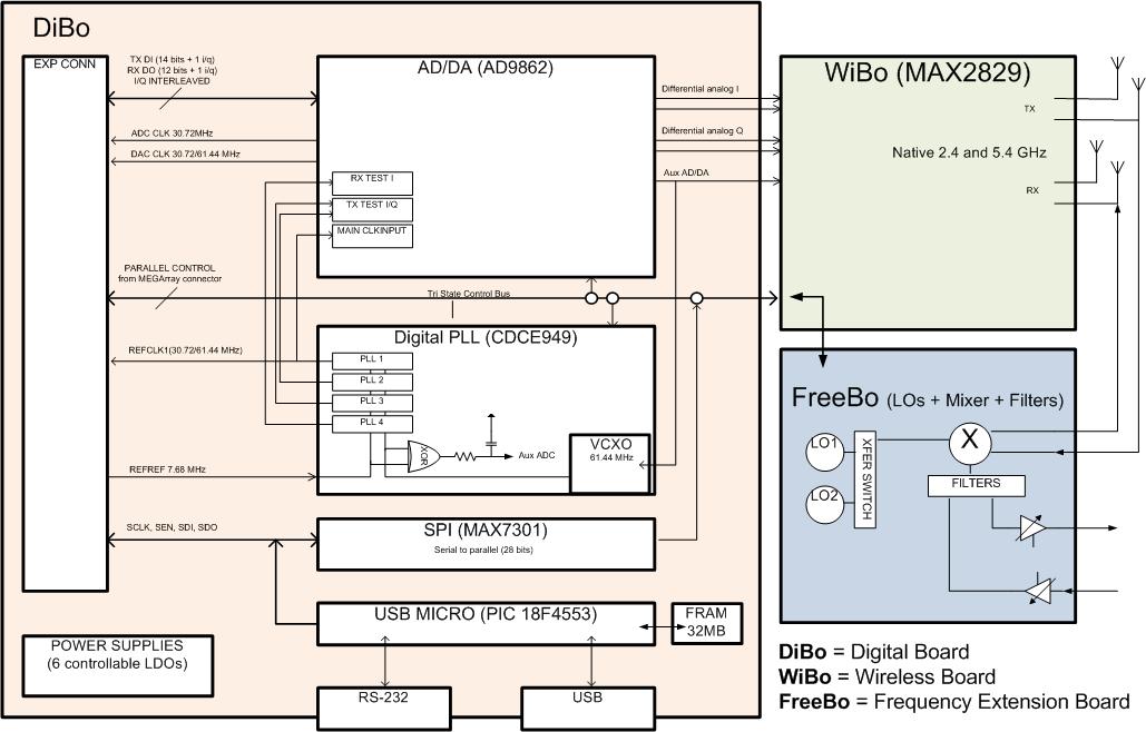
Frequency Extension Board (FreeBo)
FreeBo Registers
FreeBo registers are shown in the following table:
| Name | Address | # of Reg | Bits | Description | |
|---|---|---|---|---|---|
| ADF4350 VCO | 200 to 223 | 24 | 8 | The original 6 x 32-bit LO registers are mapped to 8 bit buss with the following mapping: R0: 200 -203, R1: 204 -207, R2: 208-211, R3: 212 -215, R4: 216 -219, R5: 220-223 | |
| | | | R3: 212 -215, R4: 216 -219, R5: 220-223 |
+-----------------------+------------+----------+------+----------------------------------------------------+
| MAX7301 RF Switch     | 224 to 247 |    24    |  8   | 12 x 16-bit registers are mapped to 24 8-bit regs  |
|                       |            |          |      | R0: 224-225,R1: 226-227,R2: 228-229,               |
|                       |            |          |      | R3: 230-231, R4: 232-233,R5: 234-235,              |
|                       |            |          |      | R6: 236-237, R7: 238-239,R8: 240-241,              |
|                       |            |          |      | R9: 242-243, R10: 244-245, R11: 246-247            |
+-----------------------+------------+----------+------|----------------------------------------------------+
|Hittit HMC629          |     1      |     1    |  8   |The upper 4 bits program the RX attenuator while the|
|RF Attenuator          |            |          |      |the lower 4 bits control the TX attenuator.         |
+-----------------------+------------+----------+------|----------------------------------------------------+
For example, to generate Fout = 3314.705 MHz (plus other LO default values), configure six registers as shown below:
- R0: 00000000101001011001110101101000
- R1: 00001000000000001011111010000001
- R2: 00000001000000000101111011000010
- R3: 00000000000000000000010010110011
- R4: 00000000100001010000000111111100
- R5: 00000000010110000000000000000101
For example, to initialize the MAX7301 chip configure the first eight registers as in the following.
- R0: 0000010000000001
- R1: 0000100101010101
- R2: 0000101001010101
- R3: 0000001101010101
- R4: 0000110001010101
- R5: 0000110101010101
- R6: 0000011001010101
- R7: 0000111101010101
To generate default setting (straight through setting) use the following configuration.
- R8: 0100010001000000 /RX switch straight
- R9: 0100110001000000 /TX switch straight
- R10: 0101010000000000 /don't care
- R11: 0101110000000000 /don't care
To generate crossed-switch setting (inputs crossed over) use the following configuration.
- R8: 0100010000100000 /RX switch cross
- R9: 0100110000100000 /TX switch cross
- R10: 0101010000000000 /don't care
- R11: 0101110000000000 /don't care
For example, “11111111” corresponds to lowest attenuation level, i.e., the maximum FreeBo gain while setting it to “10100000”, corresponds to 15 dB receiver attenuation and 45 dB of transmitter attenuation.
Attachments (5)
-
ADF4350.pdf
(797.3 KB
) - added by 14 years ago.
Analog Devices ADF4350 VCO Data Sheet
-
MAX7301.pdf
(347.6 KB
) - added by 14 years ago.
Maxim MAX7301 RF Switch Data Sheet
-
HITTITE_HMC629 .pdf
(328.9 KB
) - added by 14 years ago.
Hittit HMC629 RF Attenuator Data Sheet
-
FreeBo.pdf
(235.3 KB
) - added by 14 years ago.
FreeBo Schematic
-
FreeBo-BD.jpg
(87.5 KB
) - added by 14 years ago.
Extended Frequency SDR Board Block Diagram
Download all attachments as: .zip
Note:
See TracWiki
for help on using the wiki.